QuickStart
Step 1: Prepare equipment and development environment
Equipment Accessories List
| Accessory Name | Quantity | Description |
|---|---|---|
| Intelligent Camera Unit | 1 | Factory pre-installed |
| Camera fixing bracket | 1 | Factory pre-installed, detachable |
| Gigabit Ethernet Cable | 1 | Not included |
| Network port adapter | 1 | Factory pre-installed |
| 12V DC Power Adapter | 1 | Not included, needs to be purchased separately(It is recommended to use a 12V~3A power adapter) |
Equipment Installation
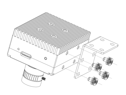
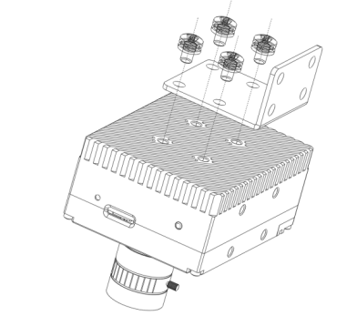
Mount the equipment onto the fixed bracket using four M68 screws, and then attach the fixed bracket to other components using another set of four M68 screws. There are two installation methods available, and you can choose the appropriate method based on actual needs.
As shown in the "Side Installation" and "Back Installation" diagrams:
Equipment Connection Topology
After installing the equipment, connect it to other peripherals for the initialization configuration. The connection topology diagram is as follows:
Method 1 (Recommended): Connect the camera via an Ethernet cable:
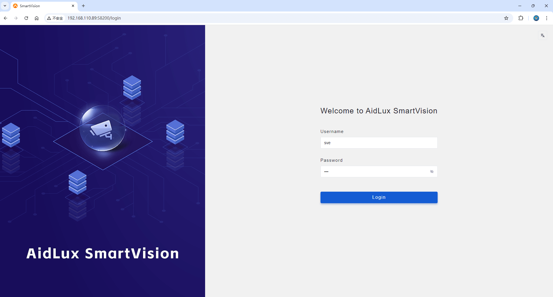
The camera device and the PC are directly connected through a network cable. Set the IP address of the PC to 192.168.1.254. After the camera device is powered on and started, enter the URL: http:// 192.168.1.123:58200/ from the PC browser to access the camera management. System, management system default user name sve, password sve
※The factory default IP of the camera is 192.168.1.123
※ PC running Windows, MacOS, or Ubuntu is supported.
Method 2: Directly operate the camera:
After powering up the camera device, connect the HDMI monitor, USB keyboard and mouse, and power on. After the device is started and the AidLux desktop system is entered, the following interface will be visible:

Click the [SV Engine] shortcut on the desktop, enter the username sve, password sve, and log in to the camera management interface.
Step 2: Configure device information
1. Initial Login
Steps:
After connecting the intelligent camera to the power source, the device will automatically boot. When the power indicator turns solid red, it indicates that the device has started successfully.
After the device is connected and powered on, use a browser on the PC to log into the camera management interface by entering the following link: http://[Camera IP]:58200/
For example, if the default IP of the camera is 192.168.1.123 , enter the following URL in the browser: http://192.168.1.123:58200/
Enter the username and password in the web interface to access the device management page.
Default Username: sve Default Password: sve
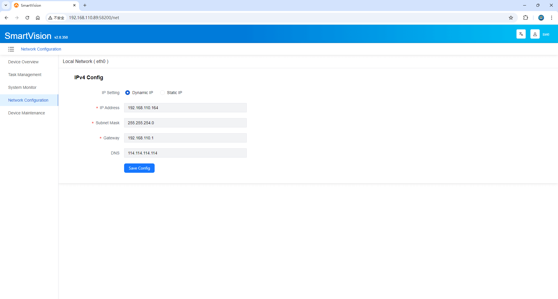
2. Network Configuration
After logging into the camera, select Network Configuration from the left-side menu to configure the IP information for the camera’s wired network.
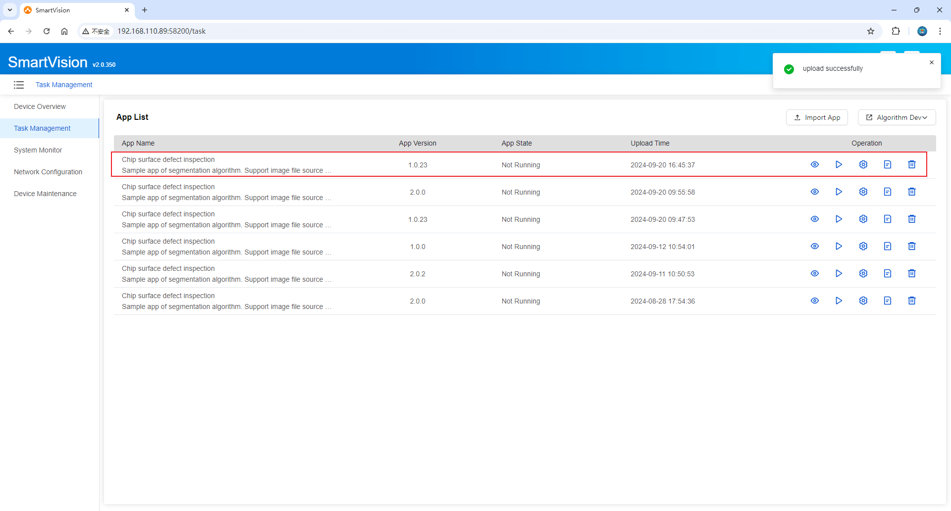
3. Task Management
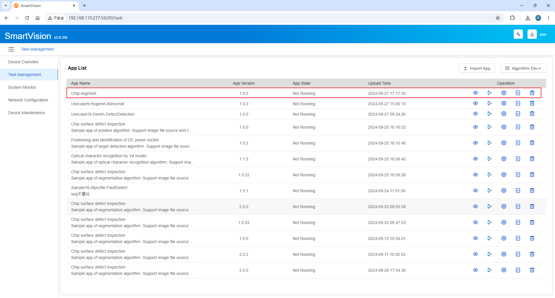
Application List
After the SmartVision Engine application is installed, two sample applications are built-in by default [Application Example (Picture Acquisition)] and [Application Example (Segmentation)]. The [Application Example (Picture Acquisition)] application does not include any inference and can be used for system and physical camera image capture debugging. The application list displays all AI application packages currently installed on the system, including the application name, version, status, and upload time. Taking [Application Example (Picture Acquisition)] as an example, we will explain the functions of the smart camera:
 Enter the Runtime Preview Interface: Navigate to the "Runtime Preview" interface to view the original and result images produced during AI inference in real time.
 Start ▪
  Stop Application: Start or stop the AI application package.
- <img src=./img/webicon_task_setting1.png" alt="setting" width="25" height= "25" style="white-space: nowrap;display: inline-block; vertical-align: middle;"/>Enter Imaging Settings Interface: Modify camera parameters, algorithm threshold parameters, and result data integration configurations.
 View Application Runtime Logs: View the log information generated during application runtime.
 Delete Application: Remove unnecessary AI application packages.

Click the Import Application Package button to upload user AI application packages (for details on package format, content, and how to build, refer to [Step 3: Build Your First Camera Application]).
Runtime Preview
View real-time data of the original and result images from AI inference, as well as statistics on the number of samples. The sample count will reset to zero after each start.
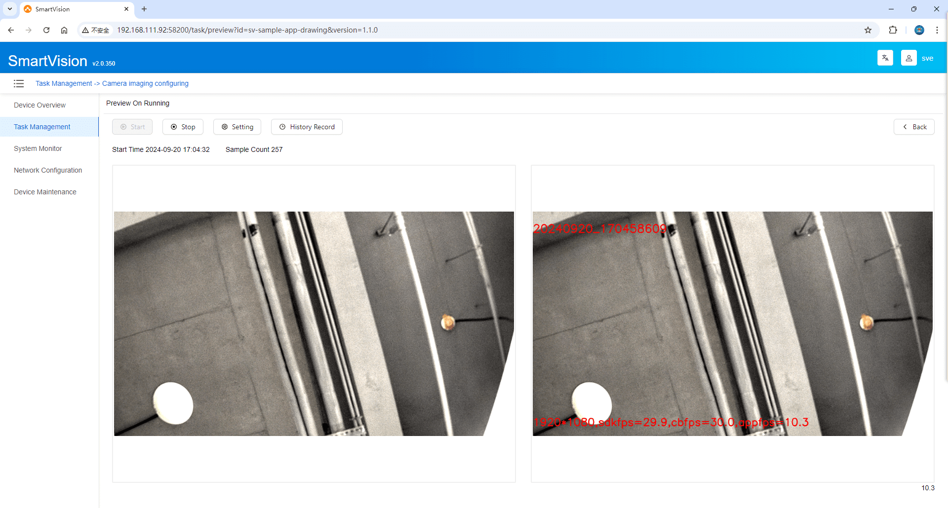
Click Start and Stop buttons to control the start and stop of the AI application package. Based on the current application package status, the corresponding button will be dynamically enabled. Once the AI application is running, it will perform target detection and generate results. The left side shows the Original Image, and the right side displays the Result Image after inference. Below is an example of the built-in algorithm application in action.
Click the Settings button to jump to the Imaging Settings interface to modify parameters. Note: This button is disabled while the algorithm application is running.
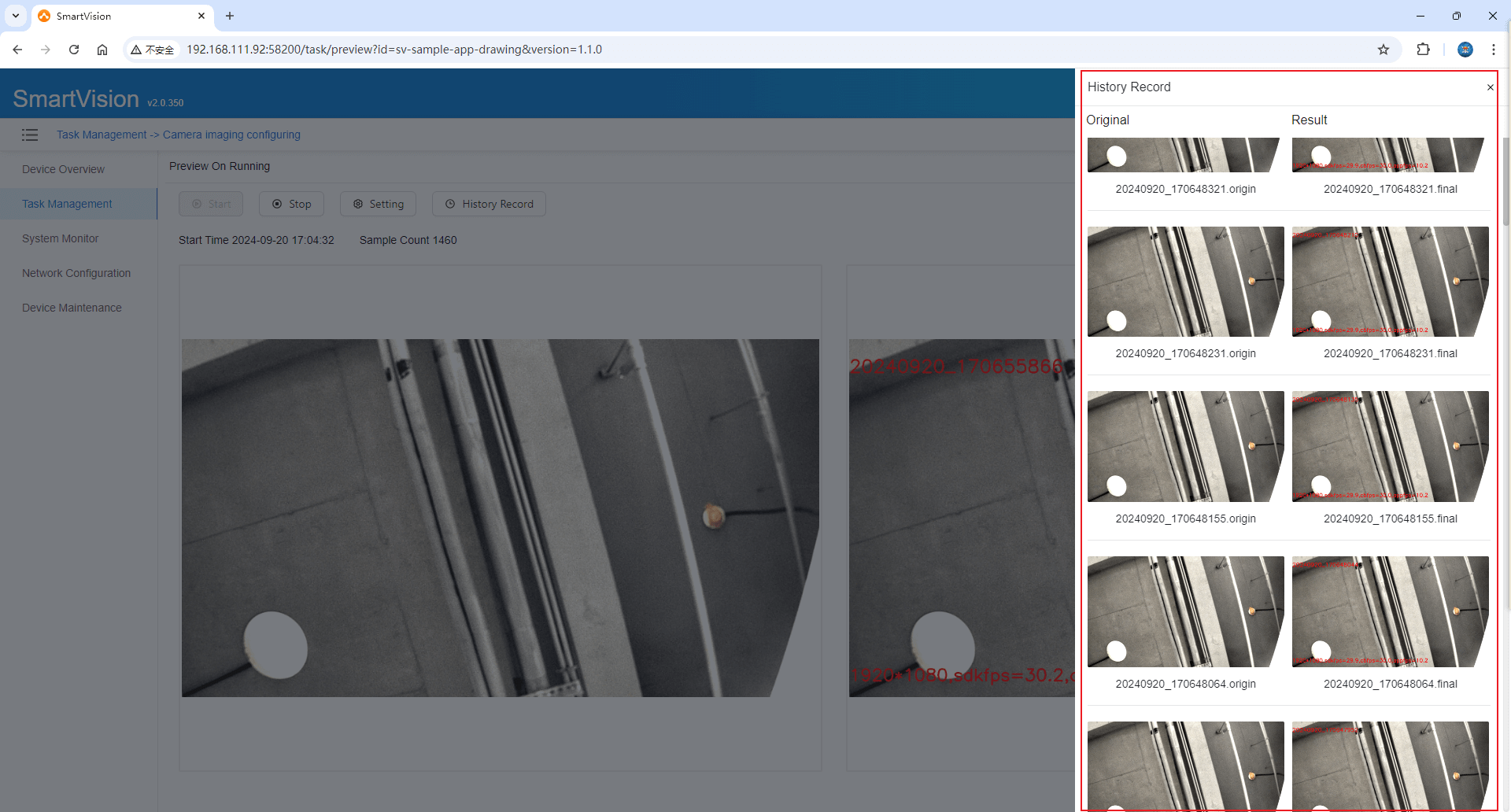
Click History to open a side panel displaying a history of original and result images after inference. Click any image to view it independently and use the Fullscreen, Zoom In, Zoom Out, and Rotate features.

Click the Back button to return to the Application List interface.
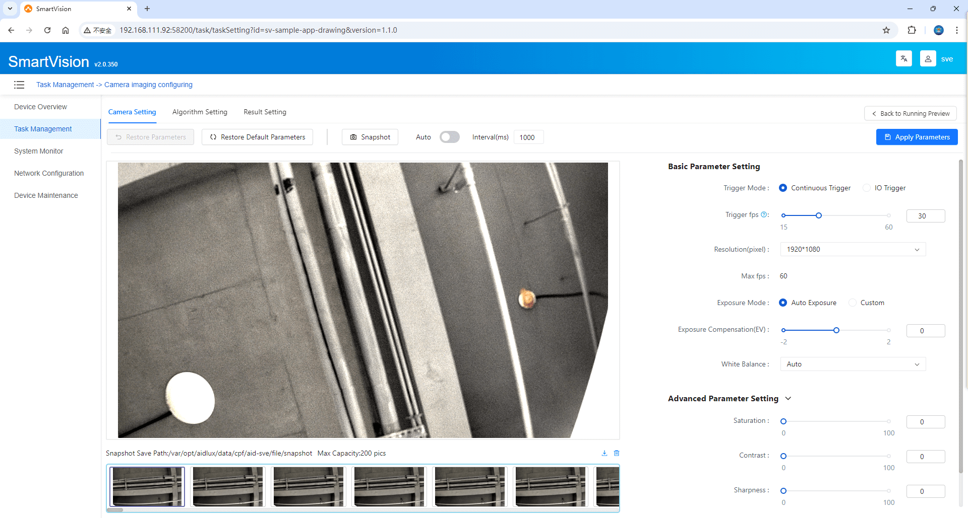
Imaging Settings
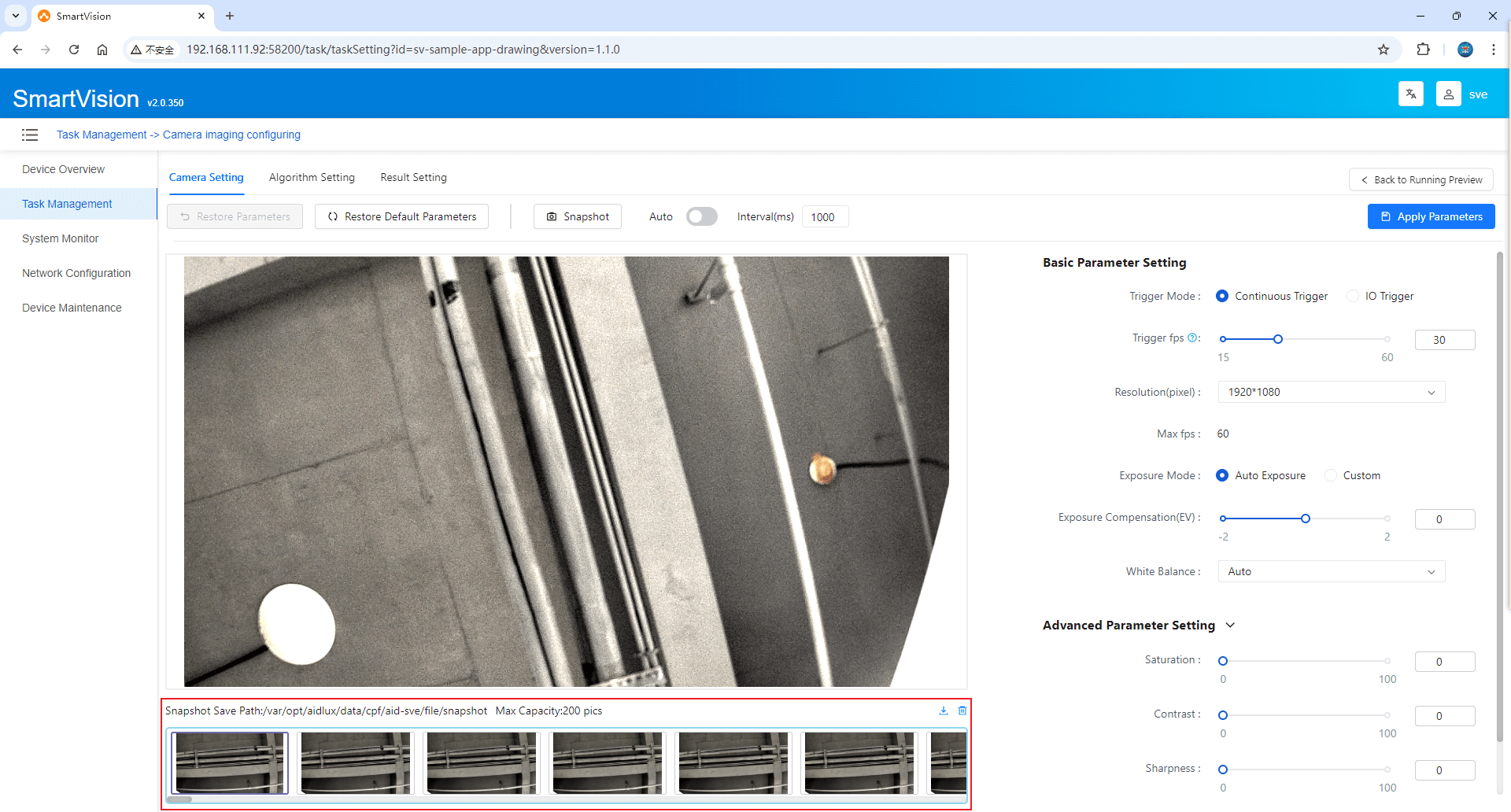
Adjust camera parameters to achieve optimal image quality. As shown below:
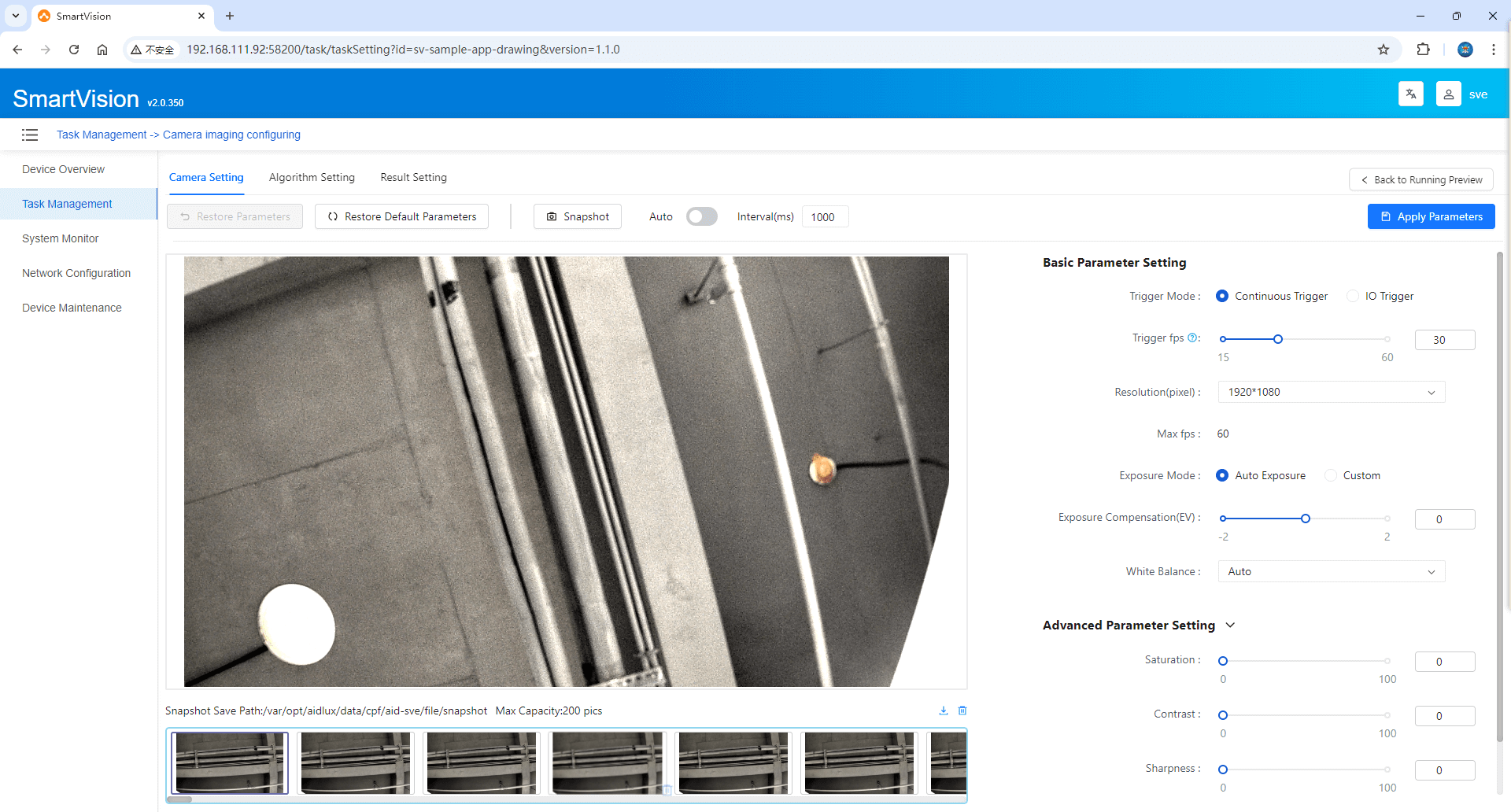
Trigger Method: Select between Continuous Trigger and IO Trigger modes.
When Continuous Trigger is selected, the configuration is automatically saved, and the camera will be opened. The captured images will be displayed in real-time. You can update camera parameters while the camera is active.
Click the Capture Snapshot button to take a photo of the current visible real-time image and display it below. Enable Auto to automatically take and store snapshots at preset intervals, displaying them below.
When IO Trigger is selected, the configuration is automatically saved, and the camera is opened. External trigger signals must be connected, and once received, a photo will be taken. The corresponding image and sample count will be displayed below.
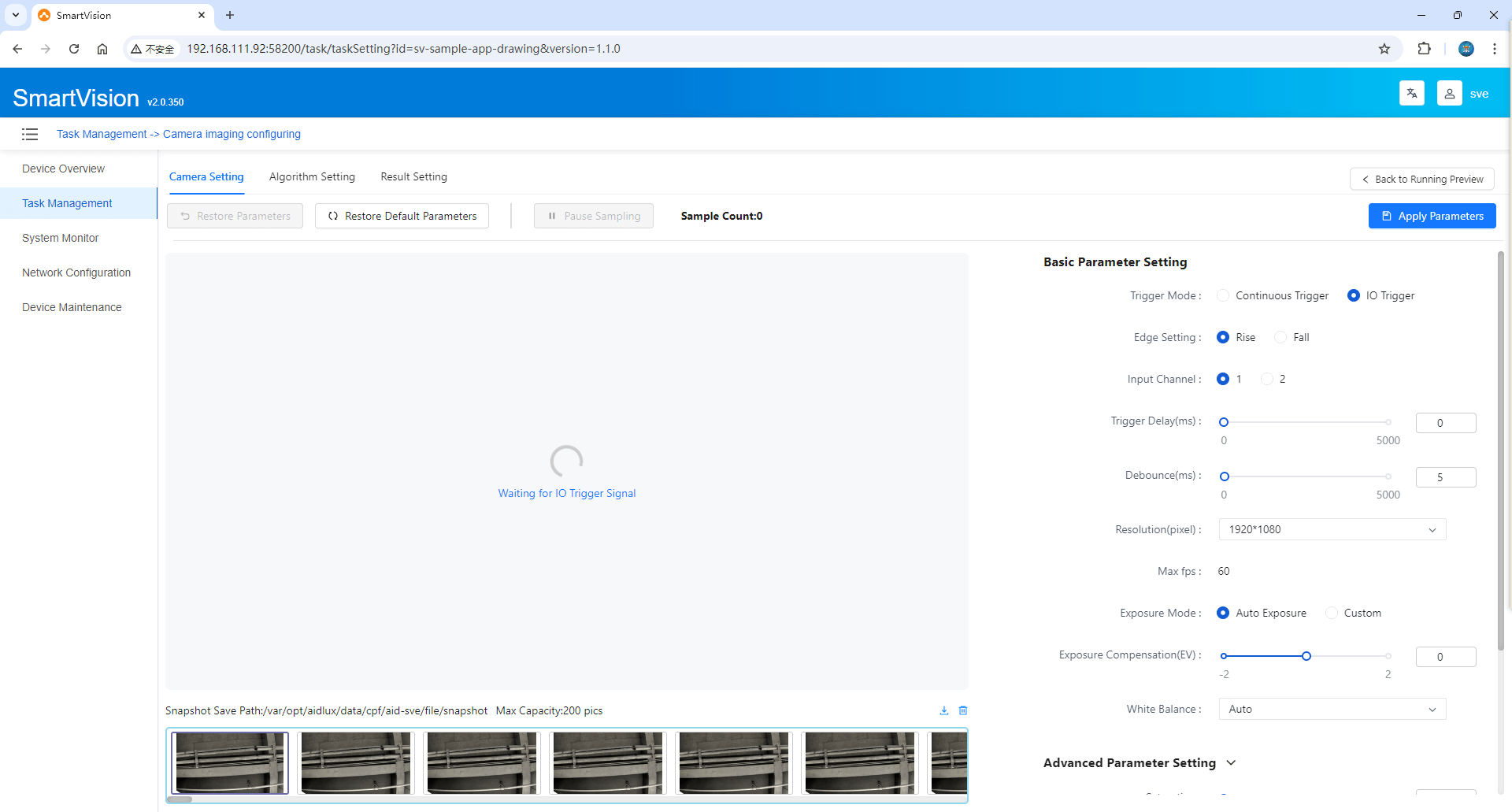
The imaging settings page allows configuration of camera parameters, including trigger settings and image parameters.
Basic Parameter Settings
- Trigger Method: When IO Trigger is selected, configure the Edge Setting and Trigger Delay (us). Edge settings include Rising Edge and Falling Edge. Select the input channel (1 or 2), and configure Trigger Delay and Debounce duration. The default delay is 0ms, and the default debounce is 5ms.
- Exposure Settings: When Auto Exposure is enabled, only Exposure Compensation is editable. When Custom is enabled, both Exposure Duration and Exposure parameters are editable.
- White Balance Settings: When Custom White Balance is disabled, it can be configured. It includes 7 white balance modes: Incandescent, Fluorescent, Warm Fluorescent, Daylight, Cloudy, Twilight, Shade.
Advanced Parameter Settings
- Saturation: Adjusts the purity or vividness of colors in the image.
- Contrast: Adjusts the difference between the lightest and darkest parts of the image.
- Sharpness: Adjusts the clarity of image edges.
- Custom White Balance: When enabled, you can adjust the Color Settings Mode, which includes Color Temperature and RGB Gain. If RGB Gain is selected, you can edit R Gain, G Gain, and B Gain.
Click Apply Parameters to save the changes. If the image does not look as good as the previous one, you can restore the previous settings by clicking Restore Parameters.
Snapshot images support One-click Export to Zip, One-click Delete, and Single File Delete. The system can store up to 200 snapshots, and when a new snapshot is taken, the oldest one is deleted automatically.
Click any snapshot to view the camera parameters associated with that snapshot independently. You can also use the Fullscreen, Zoom In, Zoom Out, and Rotate features.

Click Back to Runtime Preview to return to the Runtime Preview interface.
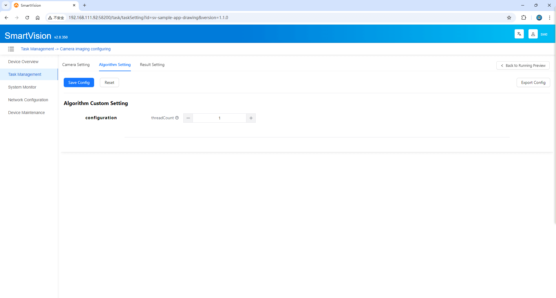
Algorithm Settings
- This interface displays threshold parameters related to the corresponding AI application. Different applications will have different threshold parameters, which can be displayed dynamically.
- Click Save Configuration to store the modified parameters.
- Click Reset to revert to the last saved parameters.
- Click Export Configuration to Local to download the current parameter configuration as a JSON file.
- Click Back to Runtime Preview to return to the Runtime Preview interface.
Result Handling Settings
The results of AI inference can be configured to integrate with external systems, as shown below:
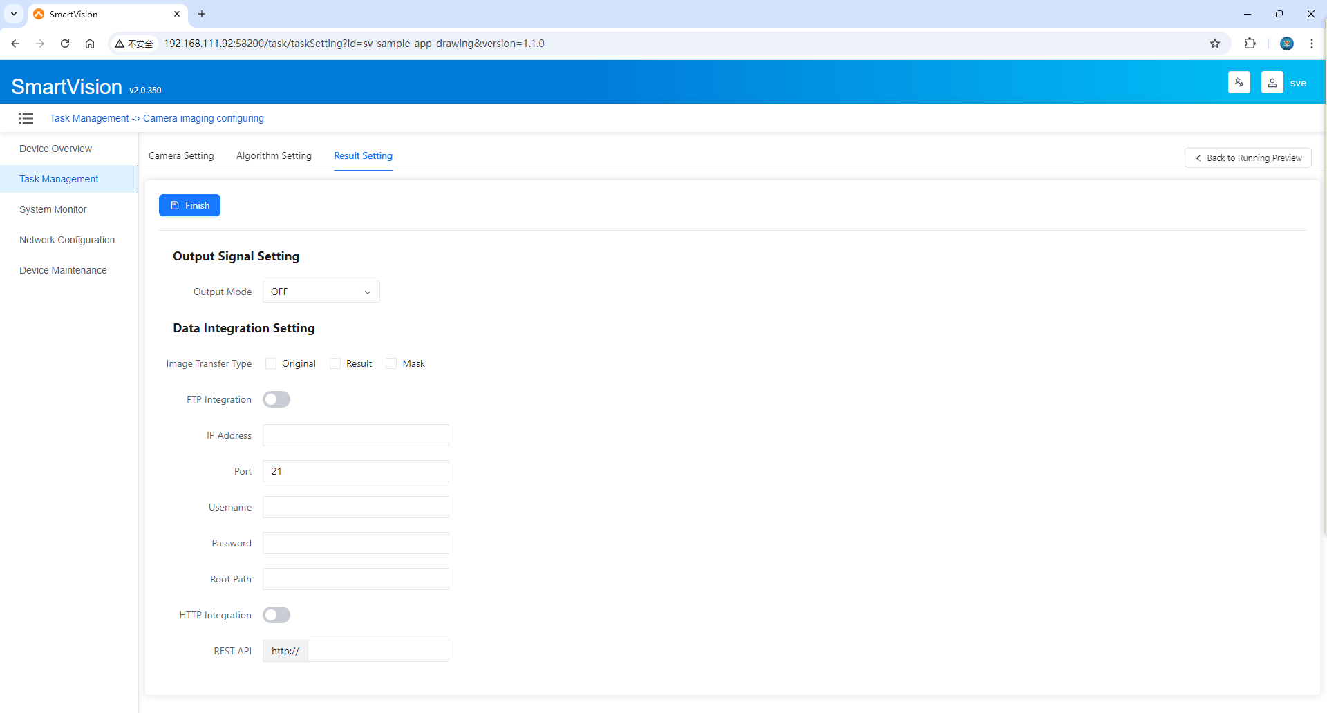
1. Output Signal Settings, integrated with an external control system. Three modes are supported: OFF, IO Signal, and TCP.
- OFF: No external signal is generated.
- IO Signal: Configure signal types for pins 1 and 2, as well as NG signal duration. Based on the pin signal definition, DO#1 corresponds to 20-9, and DO#2 corresponds to 20-10.
- TCP Signal: Configure the IP address and port.
2. Data Integration Settings, integration with external business systems.
- Image Transfer Type: The AI inference results will include "Original Image", "Result Image", and "Mask Image". Users can select which images need to be transferred based on actual needs.
- FTP Integration: The IP address, port, username, password, and root path can be configured only when the FTP integration function is enabled.
- HTTP Integration: The REST API can be configured only when the HTTP integration function is enabled. The system will use HTTP for transmission, with the content-type set to multipart/form-data, and the parameter name is
files.
Click the [Return to Operation Preview] button to switch to the [Operation Preview] interface.
Click the [Finish] button to save the settings and automatically jump to the [Operation Preview] interface.
4. Equipment Maintenance
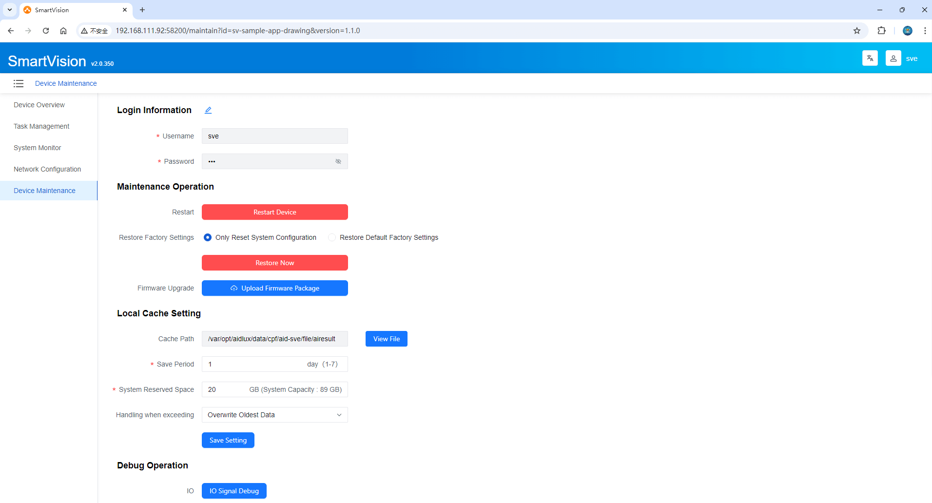
1. Login Information
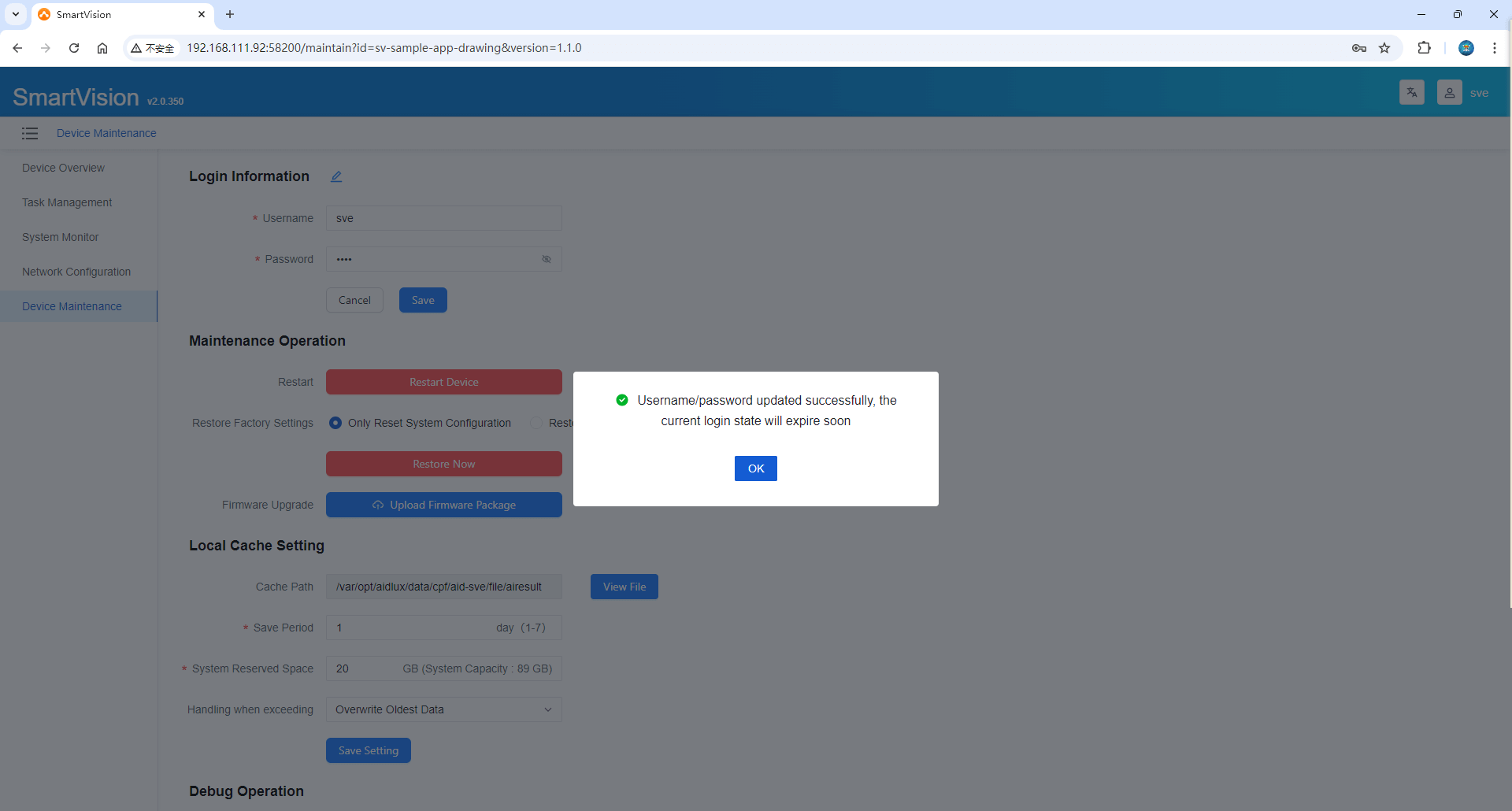
Click ![]() to edit the login information and modify the username and password. After modification, click [Save] to display a successful update pop-up window. Click [Confirm] to jump to the login page, and log in to the SVE again.
to edit the login information and modify the username and password. After modification, click [Save] to display a successful update pop-up window. Click [Confirm] to jump to the login page, and log in to the SVE again.
2. Local Cache Settings
- Cache Path: Displays the default save path, which is not editable. Clicking the [View File] button will trigger the browser to open a new page to view the AI inference result files on the corresponding environment.
- Save Period: Set the retention time for the inference result files, with a minimum of 1 day and a maximum of 7 days.
- System Reserved Space: Refers to the disk space that needs to be reserved for the operating system itself. The system capacity varies depending on the hardware environment, and the reserved space cannot exceed the system capacity.
- Overlimit Handling: Includes two methods: "Overwrite Oldest Data" and "Stop Caching Latest Data".
- Overwrite Oldest Data: The newest result data will be saved, while the oldest data will be deleted.
- Stop Caching Latest Data: The latest result data will not be saved but can be integrated externally via FTP or HTTP (the respective method needs to be enabled).
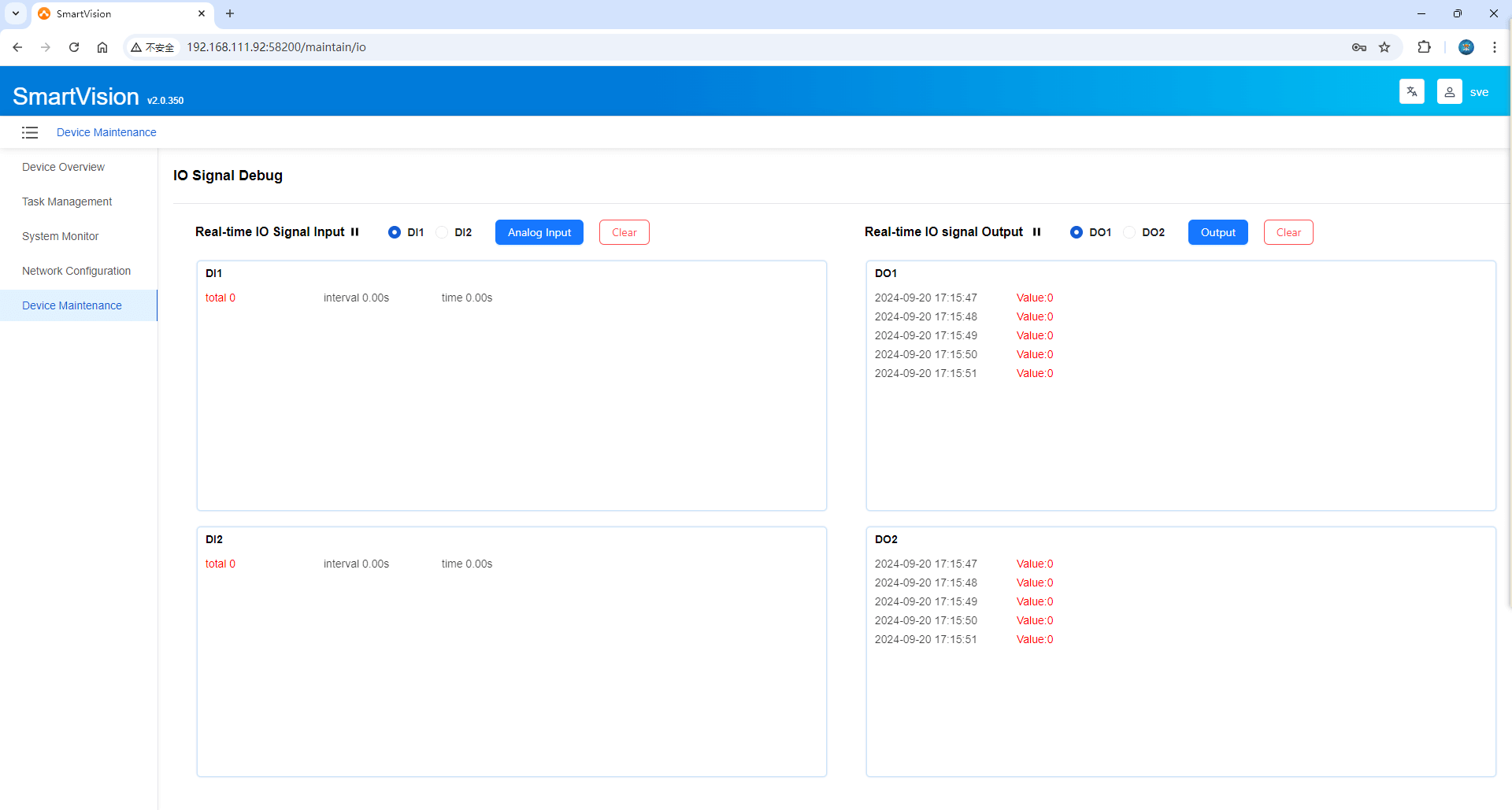
3. Debugging Operations
Click [IO Signal Debugging] to jump to the [IO Signal Debugging] interface for pre-environment debugging before using the camera to perform inference via IO Image Capture.
Step 3: Run and preview the built-in segmentation application
Take [Application Example (Segmentation)] as an example to run and preview the inference effect
Preview running effect
- Click the [ Start/Stop Application ] button in the list to run the application example.
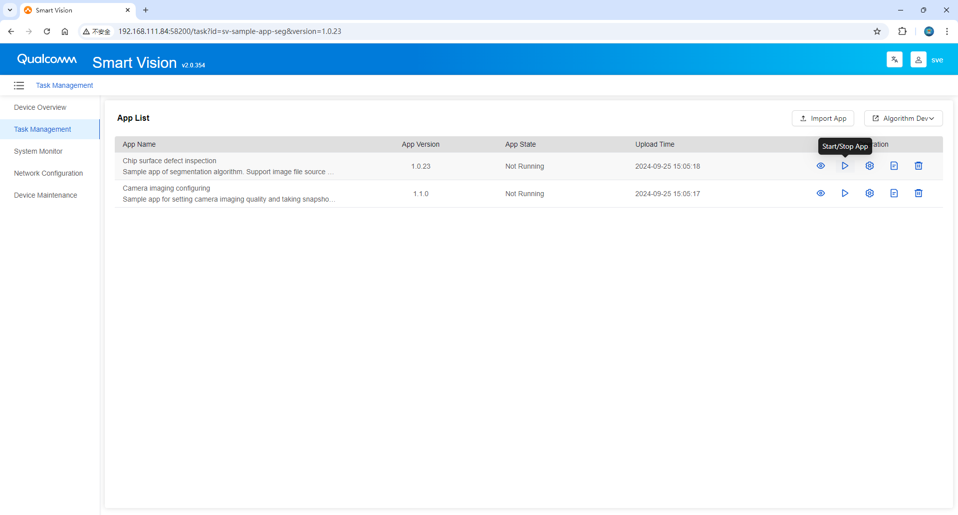
- Click the [Run Preview] button to view the running effect.

Algorithm Settings
- This interface displays threshold parameters related to the corresponding AI application. Different applications will have different threshold parameters, which can be displayed dynamically.
- Click Save Configuration to store the modified parameters.
- Click Reset to revert to the last saved parameters.
- Click Export Configuration to Local to download the current parameter configuration as a JSON file.
- Click Back to Runtime Preview to return to the Runtime Preview interface.
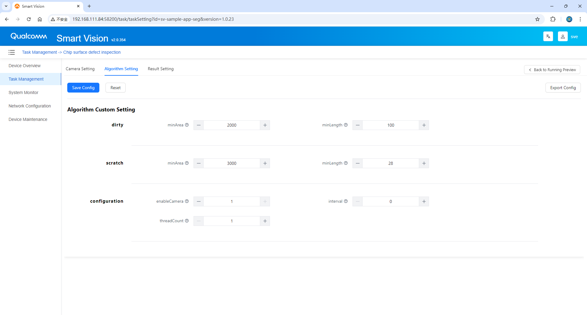
- Dirt: Dirt defects.
- Minimum area: Minimum area for dirt detection
- Minimum length: Minimum length for dirt detection
- Scratch: A scratch defect.
- Minimum area: minimum area for scratch detection
- Minimum length: minimum length for scratch detection
- Configuration:
- Camera/still image: whether to turn on the camera; 0-turn off the camera, 1-turn on the camera
- Image processing interval (seconds): Image processing interval; unit (seconds)
- Number of threads: The number of threads used by the application to actually process images, default 1
Step 4: Generate and deploy the application with one click from AI Creator
AI application generation
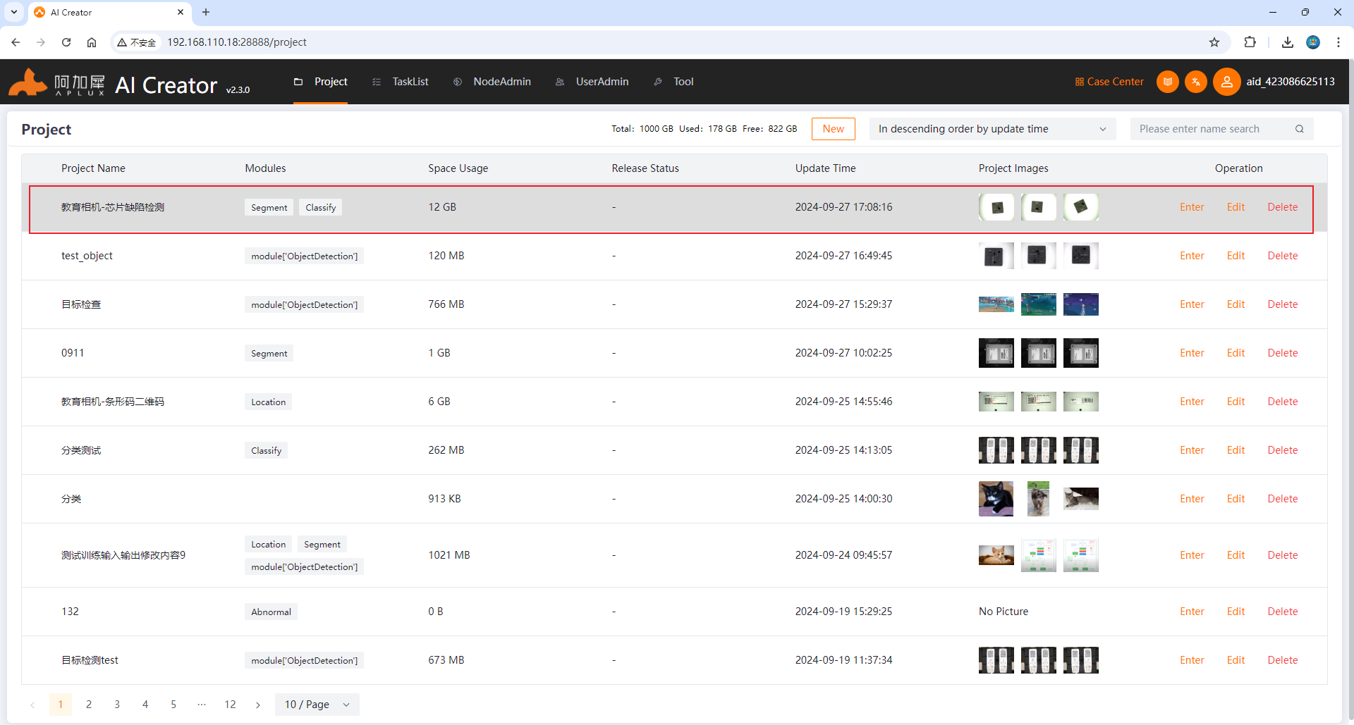
- Open the browser and log in to AI Creator. Click [Project Center] to enter the project list. Find the [Chip Segmentation] project that has been trained ( please refer to the AICreator user manual for how to train the AICreator model ), and click [Enter Project] to view the model details. As shown below:
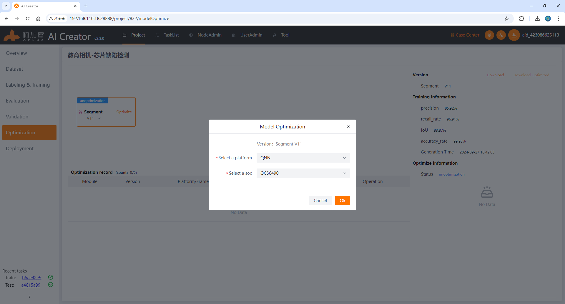
Note: Since the model is trained on the x86 platform, if you want to run it on a smart camera or edge, you need to optimize the model. AICreator has built-in AIMO model optimization function and supports one-click optimization and advanced optimization. For the chip model of the device running the model, a series of parameters are preset for one-click optimization. The user only needs to select the chip model of the device running the model. The smart camera chip model used in our experiments is QCS6490, and it is recommended to convert the model to QNN format for running.
- Click the [ Model Optimization ] tab on the left, in the optimization release interface, click [ One-click Optimization ], select the QNN format and QCS6490 chip model to complete the model optimization.
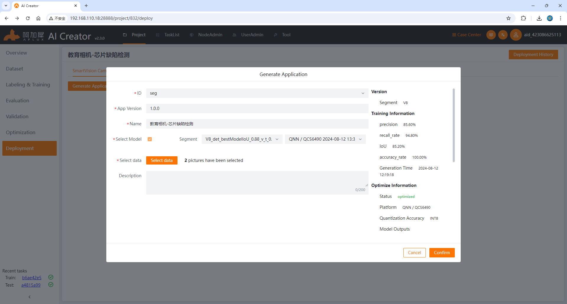
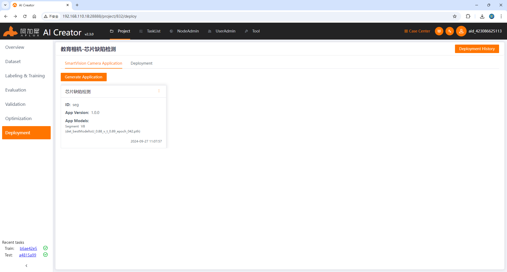
- Click the [ Deployment] tab on the left, click [Generate Smart Camera Application], fill in the application information such as application ID, application version, application name, select the image data and click OK to generate the AI application.
Deploy AI applications to cameras
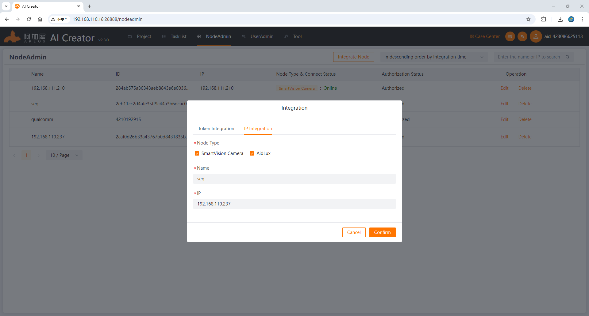
- On the node management page, click the [ Integrate Node ] button and enter the node name and the IP address of the smart camera in the pop-up form (for how to check the smart camera IP, please refer to "Step 2: Configure Device Information"). After completing the input, click OK.
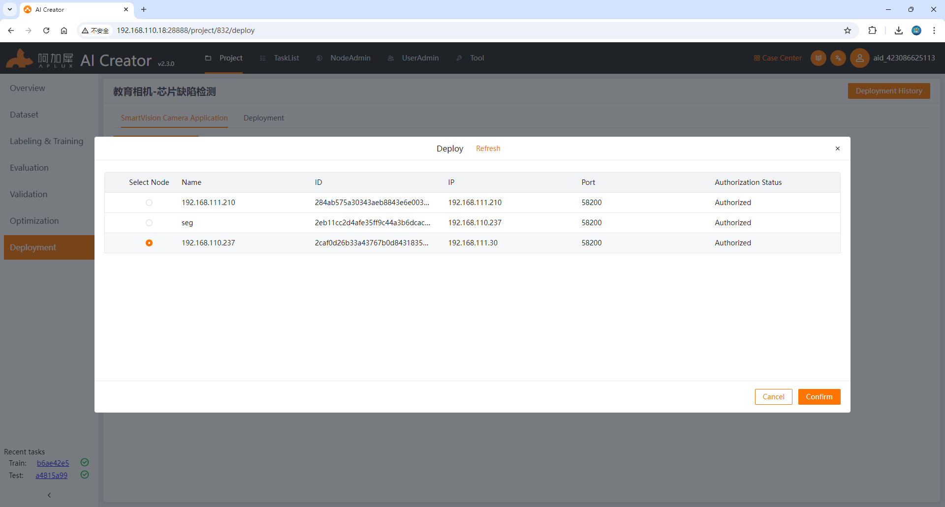
- After the smart camera is successfully integrated, return to the application generation interface of the project, select the smart camera application generated in the previous section and click [ Deploy], then select the integrated smart camera node and click [ Start Deployment]
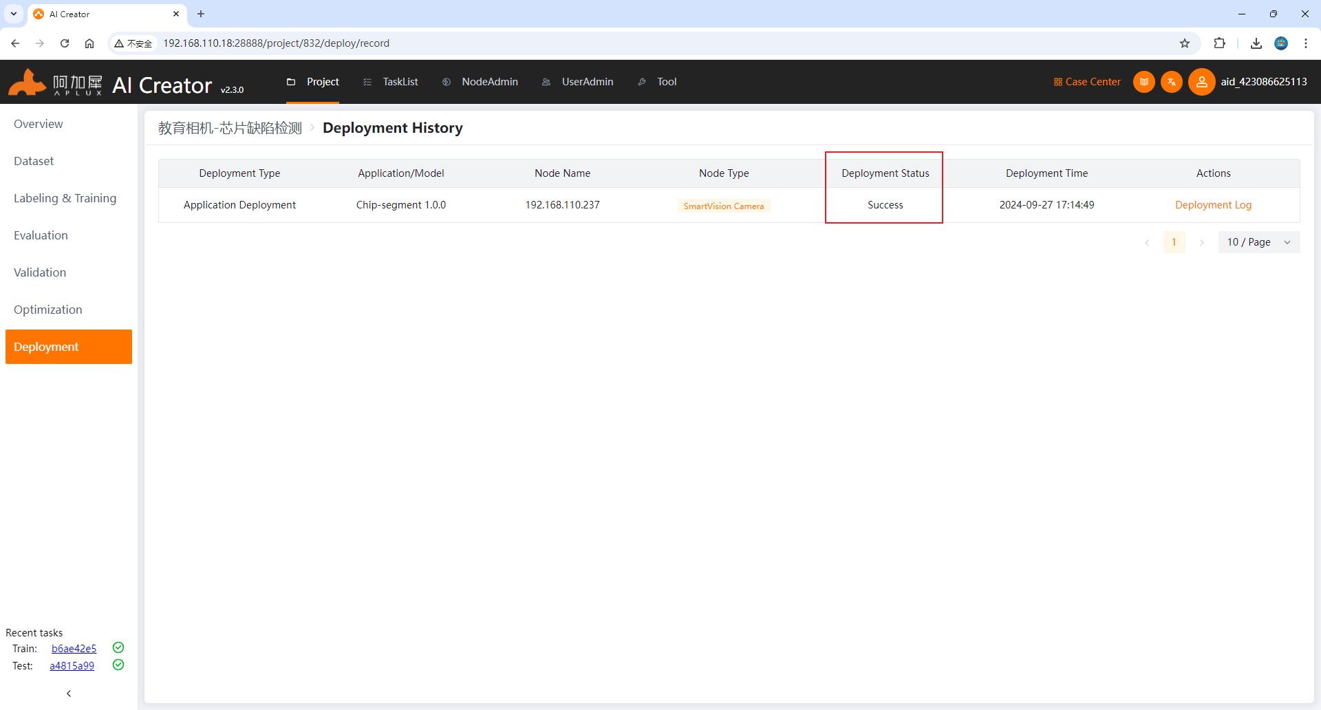
- After clicking, it will jump to the [ Deployment Record Interface]. When the [ Deployment Status] is successful , it means that the application has been deployed.
- Return to the smart camera interface to view the application list. A new piece of data has been added, which means the deployment is successful. Run it to see the inference effect.
Preview running effect
- Click the [ Start/Stop Application ] button in the list to run the application example.
- Click the [Run Preview] button to view the running effect.
Step 5: Build Your First Camera Application
I. Generate a Sample Application (with Source Code)
To help developers get started quickly, the Aidlux system provides the appc command-line tool by default, which can directly generate sample applications based on the SmartVision SDK.
The sample code is available in both C++ and Python versions.
appc Usage Instructions
Enter the Aidlux command line terminal and type "appc -h" to get usage help.

(1) Create a project
You can create different types of projects by using the command: appc init with specified parameters.
For more detailed operational information, you can get additional help using the appc init --help command.

(2) Package a project
Once development is complete, you can package the specific project using the appc package command.
Command format: appc package -p <project path>
Run the following commands on the Camera:
# Generate C++ sample code in the local directory
aidlux@aidlux:~$ appc init -t "cpp" -n demoApp
aidlux@aidlux:~$ cd demoApp# Generate Python sample code in the local directory
aidlux@aidlux:~$ appc init -t "py" -n demoApp
aidlux@aidlux:~$ cd demoAppII. Application Source Code Description
The file structure is as follows:
├── README.md
├── config                   # Configuration files
│   ├── camera.config        # Camera parameter configuration file (needs an explanation of the camera parameters)
│   ├── algorithm.config     # Algorithm parameter configuration file (needs an explanation of the algorithm parameters)
│   ├── model.config         # Model-related configuration file
├── imgs                     # Static image directory
├── lib                      # Third-party library directory
├── manager.sh               # Application startup script
├── model                    # Model file directory
│   ├── Segment_V41_0
│   │   └── det_bestModelIoU_xxx_int8.serialized.bin   # Model file
│   ├── det.txt
│   └── modelInfo.json       # Model configuration file
├── release.txt              # Application description file
├── src                      # Main program directory
│   ├── CMakeLists.txt       # CMake build file
│   ├── main.cpp             # Main application code
│   ├── main.hpp             # Header file for the main application code
│   └── model.cpp            # Main code for model loading
├── svapp # Executable file├── config # Configuration files
│ ├── camera.config # Camera parameter configuration file (needs an explanation of the camera parameters)
│ ├── algorithm.config # Algorithm parameter configuration file (needs an explanation of the algorithm parameters)
│ ├── model.config # Model-related configuration file
├── lib # Third-party library directory
├── manager.sh # Application startup script
├── model # Model file directory
│ ├── Segment_V41_0
│ │ └── det_bestModelIoU_xxx_int8.serialized.bin # Model file
│ ├── det.txt
│ └── modelInfo.json # Model configuration file
├── release.txt # Application description file
├── svapp.py # Main application codeIII. Compile and Package the Source Code for Deployment to the Camera
C++ example
1. Confirm the Camera's CMake Build Environment
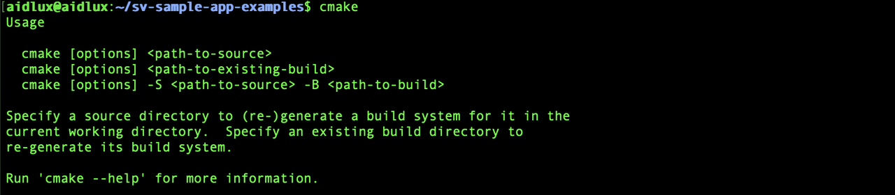
Run the cmake command to check if CMake is installed.
# CMake is not installed
aidlux@aidlux:~$ cmake
bash: cmake: command not found
If not installed, run the following commands to install CMake.
aidlux@aidlux:~$ sudo apt-get update
aidlux@aidlux:~$ sudo apt-get install cmake
Once installed, running the cmake command and seeing help information indicates a successful installation, as shown in the figure below:
2. Compile the Source Code
Run the following commands on the Camera:
# Enter the sample application directory
aidlux@aidlux:~$ cd ~/demoApp
# Run the build command
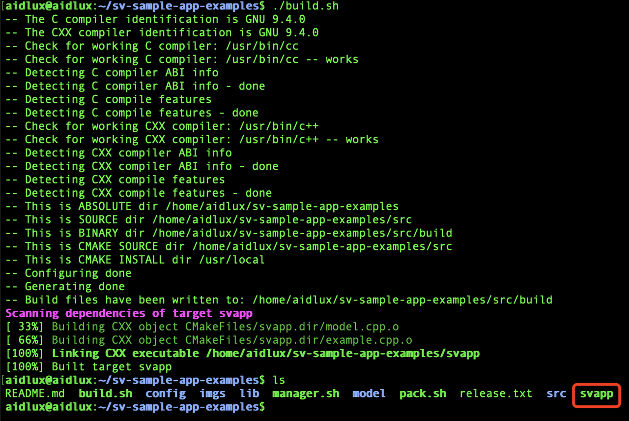
aidlux@aidlux:~/demoApp$ cd src/
aidlux@aidlux:~/demoApp/src$ mkdir build
aidlux@aidlux:~/demoApp/src$ cd build/
aidlux@aidlux:~/demoApp/src/build$ cmake ..
aidlux@aidlux:~/demoApp/src/build$ makeAfter the compilation is complete, an executable file named svapp will be generated in the root directory of the application.
3. Package and Deploy the Application
Run the following commands on the Camera:
# Run the application packaging command
aidlux@aidlux:~$ appc package -p ~/demoApp
After packaging is complete, a deployable application package will be generated in the application directory:

At this point, the entire application has been packaged. Next, proceed to the application deployment process. You can either deploy the application on this camera to preview the effect or deploy it on other camera devices.
Scenario 1: If you need to deploy the application on this camera:
Run the following commands on the Camera:
(1) Run the sve application installation command
# Run the sve application installation command
aidlux@aidlux:~$ appc install ~/demoApp.zip
💡Note
If the installation process prompts that the application already exists, you can add the "-f" parameter for forced overwrite installation:
appc install -f ~/demoApp.zip
(2) Restart the Smart Camera Application Framework
💡Note:
You need to restart the camera application framework service before the smart camera application list can reload and display the unpacked application.
# Enter the smart camera application framework directory
cd /opt/aidlux/cpf/aid-sve/

# Restart the camera application framework
sudo ./manager.sh restart
(3) Open the camera management webpage, go to [Task Management], and check the deployed application:
If the sample application appears in the application list, it means the deployment was successful.
Scenario 2: If you need to deploy the application to another camera, first copy the application package to the PC
Run the following commands on the PC: (1) Copy the application package to the PC
# Copy the packaged application from the camera to the local PC
scp aidlux@[camera IP]:/home/aidlux/demoApp.zip ./
(2) Open the management webpage of the other camera, go to [Task Management], click [Import Application Package], and select the application package from the PC.
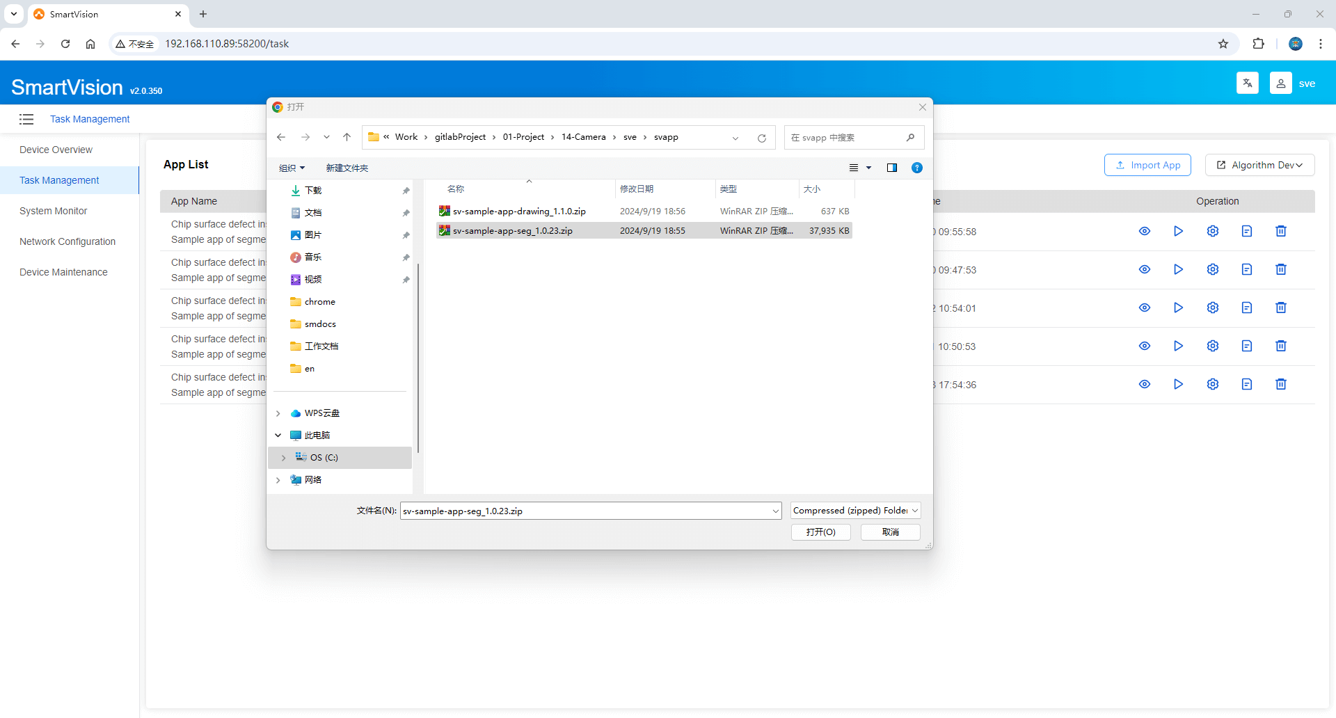
After importing, if the sample application appears in the application list, it means the deployment was successful.
IIII. Preview the running effect
- Click the [ Start/Stop Application ] button in the list to run the application example.
- Click the [Run Preview] button to view the running effect.